This project came up when I was testing some PIC18 microprocessors. I discovered the PIC18F13K50 MCU which has a build in USB controller and comes with a decent amount of peripherals.
My main interest was the build in USB controller since it reduces the need for an external USB-Serial converter.
This saves board space and money.
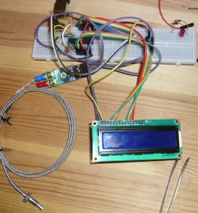
The goal was to set up a serial connection through a virtual COM port with the MCU. Since I wanted also to test some of the peripherals I connected a MAX6675 Cold-Junction-Compensated K-Thermocouple-to-Digital Converter, which I had laying around, and which has a SPI interface. Additionally I connected a LCD 2×16 display.
This construction is supposed to determine the temperature with the MAX6675 thermocouple, display it on the LCD and print it to the serial interface. This functionality is useful for temperature logging on the computer and for some temperature controlled tasks like for example controlling a PCB re-flow oven.
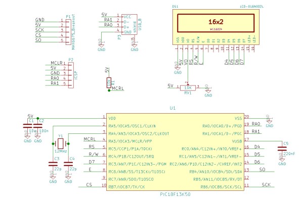
The schematic looks the following:
The first thing I implemented was the USB interface. As a starting point I used the Microchip Libraries for Applications (MLA) [1]. This libraries include a lot of examples, also for USB.
The PIC18F13K50 is a very low budget MCU and comes with very little memory. The USB-serial example eats already up most of the space on the MCU :(. In order to save space one can reduce the input/output buffer size. This can be done in the usb_config.h. There one changes the two lines
#define CDC_DATA_OUT_EP_SIZE    16
#define CDC_DATA_IN_EP_SIZE     16
I copied all files needed for USB into a local project folder instead of using it directly from the MLA. This gives some more flexibility in case of editing some of the files for example when debugging.
LCD
In order the get the LCD working the XLCD library from Microchip is used. This library comes together with the MPLAB X IDE.
But is unfortunately not as easy to use as one thinks it is!
When using it “as is” the ports for the LCD are in some way hardcoded which is very inflexible. The ports can be configured in the xlcd.h but will not change everywhere in the code if just the header is edited, since the library is already pre-compiled and therefore the whole library needs to be recompiled.
Since this is kind of a strange way (maybe there exists a better way), I made a local copy of the files in the project folder.
This makes it possible to edit the files and compile everything together with the project.
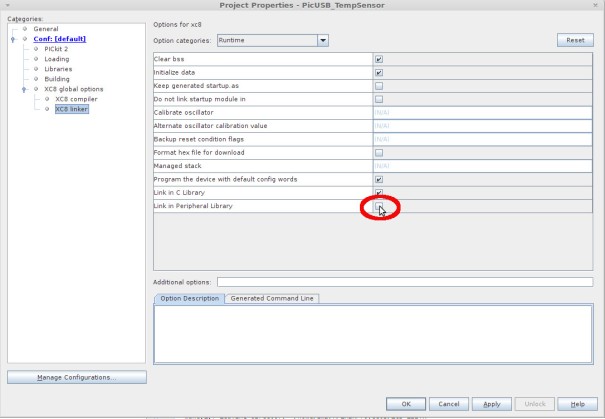
Since the XLCD library is also in the “Peripheral Library” of Microchip, which is by default linked to the project, one can get some very ugly surprises. It is therefore needed to disable the linking of the Peripheral Library.
This can be done in the Project properties – XC8 linker – Link in Peripheral Library (disable it)
The lines in the XLCD.h can be adjusted:
/* DATA_PORT defines the port to which the LCD data lines are connected */
 #define DATA_PORT      		PORTC
 #define TRIS_DATA_PORT 		TRISC

/* CTRL_PORT defines the port where the control lines are connected.
 * These are just samples, change to match your application.
 */
 #define RW_PIN   LATCbits.LATC4   		/* PORT for RW */
 #define TRIS_RW  TRISCbits.TRISC4    	/* TRIS for RW */

 #define RS_PIN   LATCbits.LATC5   		/* PORT for RS */
 #define TRIS_RS  TRISCbits.TRISC5    	/* TRIS for RS */

 #define E_PIN    LATCbits.LATC6  		/* PORT for E  */
 #define TRIS_E   TRISCbits.TRISC6    	/* TRIS for E  */
The used ports should be configured as digital output port
    //LCD configuration
    TRISC = 0x0; //TODO select specific pins! maybe in the LCD file??
    LATC = 0x0;
In order initialize the LCD one calls the function
OpenXLCD(FOUR_BIT & LINES_5X7);
This sets the LCD to work in 4 data line mode, and configures the library for multi-line with 5×7 pixel.
This is the standard for 16×2 displays.
In order to have simple command to write a line in the LCD I have defined two macros one for each line of the display. I have chosen this approach over a function since it seems to produce a little bit smaller code, compared to using a function. The compiler does not optimize enough in the free version. More about this later.
#define writeLine1(s) WriteCmdXLCD(0x80); __delay_ms(15); putrsXLCD(s); while(BusyXLCD());
#define writeLine2(s) WriteCmdXLCD(0xC0); __delay_ms(15); putrsXLCD(s); while(BusyXLCD());
MAX6675 Cold-Junction-Compensated K-Thermocouple-to-Digital Converter
Communication with the MAX6675 [2] happens via the SPI serial bus. The PIC has a hardware implementation of this protocol, which requires the setting of the right register bits and then just reading and writing into the buffer/shift-register.
In theory this sounds simple, in practice it can be challenging.
The MAX6675 has a chip-enable pin which at the same time also acts in order to trigger temperature capture.
Therefore one has to implement some routine which turns the pin on and off and keeps it switched on/off for a certain time.
The data processing inside the MAX6675 takes some ms.
The chip select (CS) pin is by default “HIGH” which means OFF for the chip. When the CS pin goes low data can be read from the SPI register. 16 bits should be read, which represent a sign bit, 12 bits temperature information and 3 status bits.
By bit-shifting the 16 bits by 3 to the right one gets rid of the stats bits.
In order to get the temperature in Celsius one needs to divide the value one gets from MAX6675 by four.
This is done by another bit-shift of two. In total shifts by 5 bits to the right. In order to make the computation as easy as possible the fraction is neglected. But the accuracy of this breakout board construction is probably anyway not that exact.
Some SPI routines were developed in order to set up the bus and read the data. It is important to keep in mind that when reading SPI for each bit, which is received one bit also has to be send by the controller. These bits can be dummy bits and the MAX6675 does not even have a data input. SPI is one bit shift in, one bit shift out.
The SPI code looks the following:
#define   SSPENB        0b00100000           // Enable serial port and configures SCK, SDO, SDI
#define SPI_Init() SSPSTAT =0b00111111; SSPCON1 =0b00010010; SSPCON1 |= SSPENB;

unsigned char ReadSPI(){

    //PIE1bits.SSPIE = 0;

    //PIR1bits.SSPIF = 0;     //Clear interrupt flag
    //Write into the buffer to start the transfer
    //SPI needs dummy a byte for transfer to read
    //since write and read happen syncrone
    SSPBUF = 0x01;// initiate bus cycle

    while(!SSPSTATbits.BF);
    //while(!PIR1bits.SSPIF); //wait until cycle complete
    return SSPBUF;
}
Again here the init function is a macro in order to save space on the chip.
The whole source code can be found in GitHub.
The sad part of the Free XC8 compiler
With the free version of the XC8 compiler from Microchip the project compiles and eats up 8168 bytes of the 8192 bytes of program memory. In the compiler output it is pointed out that if one would have the pro version of the XC8 compiler:
Running this compiler in PRO mode, with Omniscient Code Generation enabled,

often produces code which is 60% smaller and at least 400% faster than in

Free mode. The MPLAB XC8 PRO compiler output for this code could be

4900 bytes smaller and run 4 times faster.
So it would basically only use half of the space. This is a sad statement from Microchipc since it is against all people who would like to use their products for hobby and experimentation and do not want to buy a commercial license. ATMEL is on that perspective much better with their free compiler chain.
The worst part is that one is forced to write ugly code in order to save some bytes. Also a wrong performance feeling as given.
If trying out the code, it should be mentioned that one needs also to start the serial read on the computer to get the LCD updated, some logic had to be removed, which handled this in a better way, in order to save space.
[1] http://www.microchip.com/pagehandler/en-us/devtools/mla/home.html
[2] https://datasheets.maximintegrated.com/en/ds/MAX6675.pdf
The described code can be found on GitHub
https://github.com/digibird1/PIC18F13K50_USB_Temp_LCD
It can be checked out with:
git clone https://github.com/digibird1/PIC18F13K50_USB_Temp_LCD


