Playing with electronics one sooner or later comes to a point, where one wants to look at signals. This can be analogue or digital and with different speed. In the university the most natural thing would be to connect a scope and look at the signal. Unfortunately scopes are very expensive and so long I was not willing to buy one. Working with signals in the low kHz frequency area, a sound card can provide a perfect solution to look at signals.
I used up to now a very cheap USB sound card from Ebay for around ~1 Euro. Which provided 2 channels in combination with one of the Linux sound card scopes.
With further interest in faster electronics the sound card solution was not good enough.
So I searched for a cheap way to get something faster:
A perfect solution is to use a ADC (Analogue Digital Converter). And hey one of these comes together with the Arduino. Per default the ADC of the Arduino Uno provides a speed of approx 200kHz at 10 bit resolution. Changing some registers this can be increased up to 1MHz without too much loss in resolution.
Descriptions how to do this can be found in the Arduino forum.
 // set prescale to 16
  sbi(ADCSRA,ADPS2) ;
  cbi(ADCSRA,ADPS1) ;
  cbi(ADCSRA,ADPS0) ;
But what to do when one wants to get even faster?
Arduino and an external ADC
One way is to connect a external ADC to the Arduino and use the Arduino to read it out and send the data to the PC, for further data processing.
A 6 bit ADC was chosen “CA3306” from Intersil. The main reason for this is that it provides a parallel read out, works with 5V, goes up to 15M samples/s and is easy to handle. Furthermore this chip is very cheap available on Ebay. Even if 6 bit is not much it provides a very good start position to play with these kind of electronics. And even with 6 bits one can already do a lot.
To archive the fastest performance one needs to go away from the Arduino language and needs to manipulate the registers by hand, turn off interrupts and more low level operations. But doing this one learns a lot and can optimize up to the limit.
The first step is that we need a data structure to save our results:
struct data{
  long Time;
  //unsigned int Values[800];
  char Values[1600];
} Data;
The structure will save the 6 bits we get from the ADC in a char (8 Bits) and it will save in Time the time it took to collect the 1600 samples. Knowing the time to collect the samples, we know the sample rate which we need in order to plot for example the signal.
The ADC needs a clock signal which make the ADC analyse the input signal. This can be archived by putting a digital pin on the Arduino high and low and then read the ADC, connecting an external oscillator to the ADC or generate a clock signal with the Arduino itself. The first approach with turning a digital pin high and low and then do the readout is the most intuitive but does not provide the max performance. Since turning the digital pin high and then low costs CPU cycles and with this time.
Much better performance can be archived by using an external oscillator or a 8MHz clock signal from the Arduino which does not cost cpu cycles and only use the cpu for read out.
With this method up to 5M samples per second can be archived.
To activate the 8 MHz clock signal on the Arduino the following code has to be called in the setup() function:
   // set up 8 MHz timer on pin 9
  pinMode (9, OUTPUT);
  // set up Timer 1
  TCCR1A = _BV (COM1A0);  // toggle OC1A on Compare Match
  TCCR1B = _BV(WGM12) | _BV(CS10);   // CTC, no prescaling
  OCR1A =  0;       // output every cycle
This puts a 8 MHz clock signal on Pin 9 which we can connect with the clock input of the ADC.
The next step is now to read out the ADC as fast as possible:
To not get disturbed by interrupts we turn them off during the reading and turn them on again.
Interrupts are very important for the serial communication, therefore it is important to turn them on again.
void loop() {

  noInterrupts();
  readValues();
  interrupts();
}
The reading itself is done in the function readValues();
Before putting the code there I want to explain why it is written in this form even though it looks very ugly and spaghetti like.
For performance reasons this has to happen in low level again:
The ports A0-A5 are used as digital ports with the register PINC.
After this we can read out all 6 bits in one go by reading out the register of the port.
This is much more efficient compared to use digital read from the Arduino library. And makes also sure that all the bits belong to the same state of the ADC.
The readout is performed by a simple call:
Data.Values[i]=PINC;
The most natural thing from a programmers point of view would be to write a for loop, looping over the 1600 samples and reading out in each step the 6 bits of the Arduino port.
for(int i=0;i<1600;i++)
    Data.Values[i]=PINC;
From a performance point of few this is not optimal: First the integer “i” has to be counted up and it has to be checked if “i” is still smaller then 1600.
To writhe the code in the form:
void readValues(){

  long Time=micros();
  Data.Values[0]=PINC;
  Data.Values[1]=PINC;
  Data.Values[2]=PINC;
  Data.Values[3]=PINC;
  Data.Values[4]=PINC;
  Data.Values[5]=PINC;
  //.....
  Data.Values[1596]=PINC;
  Data.Values[1597]=PINC;
  Data.Values[1598]=PINC;
  Data.Values[1599]=PINC;
  Data.Time=micros()-Time;//Calculate how long we where taking data
}
is much more beneficial since CPU cycles are only used in order to read the input pins.
After the readout the structure is send via the serial bus to the computer for further processing.
void loop() {
  noInterrupts();
  readValues();
  interrupts();

  sendStructure((char *)&Data, sizeof(Data));
  delay(10);
}
with
void sendStructure( char *structurePointer, int structureLength)
{
  int i;
  for (i = 0 ; i < structureLength ; i++){
    Serial.write(structurePointer[i]);
    if(i%32==0)Serial.flush();
  }
  Serial.write(0xFF);//Stop bit in order to tell data is complete
  Serial.write(0xFF);
  Serial.flush();
}
The data is send here byte by byte and the transfer is finished with two stop bits to make clear that the data transfer is finished.
How to continue processing with the data will be explained in a different post.
The ADC electronics
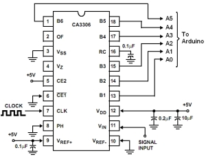
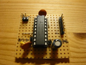
To connect the ADC with the Arduino is straight forward. It is just to connect the 6 input pins of the Arduino with the 6 output pins of the ADC.
To make the ADC work capacitors, voltage and ground need to be connected with the ADC IC.
 |
 |
Connecting everything together
Now the ADC can be connected to the Arduino and the Arduino can be loaded with the readout program.
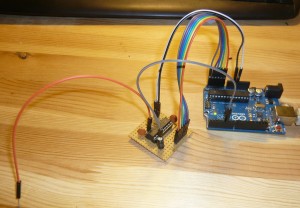
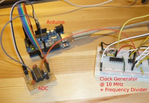
The cable in this picture which is not connected is the cable for the input signal. Clock, voltage and Digital out are connected with the Arduino.
The clock signal is here the 8MHz signal from the Arduino itself.
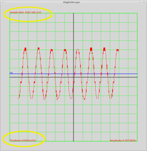
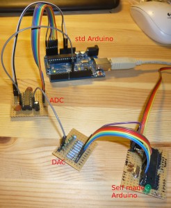
To test the functionality an analog input signal of around 30 kHz is generated using a second Arduino (self made) together with a DAC. (See post of the Arduino Soundcard project).
Reading out and analyzing the data the Arduino sends to the computer one can get a feeling about the performance.
|
|
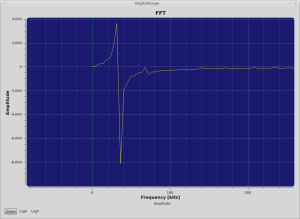
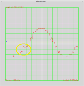
The picture on the right shows the collected data, together with information about the sample rate and the timebase. A FFT is performed on the left showing a peak around 30 kHz. A sample rate of around 5 MSPS is reached in readout.
Shows that the sine looks a bit step function like. The reason comes from the DAC which has only 6 bit! Also the ADC is only 6 bits leaving 64 values for 0 to 5 V.
Since I have no faster analog signal source further tests are done with a digital square wave source. For this a clock generator @ 10 MHz is connected to a 7 stage frequency divider. This provides the possibility to generate frequencies signals of 10/(2^x) where x goes from 0 to 7.
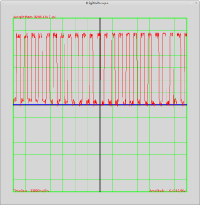
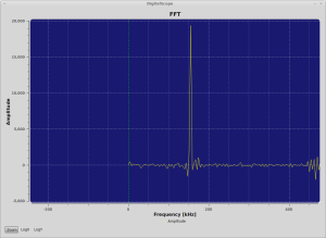
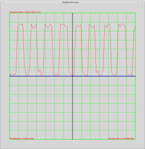
Starting with a 156 kHz square wave: 10MHz / 2^6 = 156 kHz
|
|
We see that we can record a nice square wave at around 156 kHz with our setup.
Zooming in into the record we can see a bit more details of the square wave and also that we have a lot of sample points for one period.
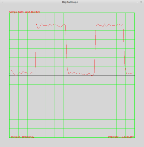
It should be noted that if one wants to analyze a very low frequency due to the limitation of space on the Arduino and the limitation of only 1600 sample points it can be necessary that one reduces the sample speed by some delays.
Limitations can be reached when going to even higher frequencies. Tests where performed with a 625 kHz square wave signal (10 MHz / 2^4 = 625 kHz).
One can clearly see that the amount of sample points to sample one period of the signal gets less and less. Going much further means higher and higher uncertainties when a period really starts and stops, due to the gap between the samples.
The code for the Arduino can be found on GitHub:
https://github.com/digibird1/Arduino/tree/master/Scope2_ExtADC
It can be checked out with:
git clone https://github.com/digibird1/Arduino/tree/master/Scope2_ExtADC
[…] Arduino as a 5M Sample Osciloscope […]
First Thanks for sharing such an interesting idea. Please may you explain the part :
” after structure is send via the serial bus to the computer for further processing” how can we draw the graphs you’d posted by the end . Thankyou
Hi, I work on an Atmel MCU/arduino based project that need a high precision ADC for measuring a watch sound signal (one tic is about 0,015s to 0,020s long and divides in three parts that need to be analyzed later: https://www.dropbox.com/s/7nar8fn95rr7lwx/watch%20signal.jpg?dl=0) this method seems to be the perfect solution but you write about using an external oscillator, how can I archive a maximum precision not only in term of voltage precision but also in sample time precision? I was looking to a TCXO oscillator or that kind of precision. Hope you can help me or show me some search path to find the answer 🙂
Thank you!
(sorry for my english, I hope this is clear enough)
First of all your project is excellent.
it helps me soo much in terms of arduino codes.
I am trying to plot it by using Matlab
but I couldn’t get data array smoothly.
Could you post how to plot acquired data ?
I would like to say that it is a really interesting proyect.
I have to work in a very similar proyect with a higher sample rate, and your sharing help me to understand lots of things.
However, I have two doubts and I would appreciate if you could clear them up:
1) You use the 8MHz clock signal of the Arduino to clock the external ADC, and the C programm is running as well at 8MHz frecuency.
So, doesn´t it mean that you are sampling at 8Msps? Where is the time lose from 8Msps to 5Msps?
2) This concept in your proyect means that the main program and the external ADC, both need to be clocked at the same frecuency, doesn`t it? Otherwise it wouldn´t be possible to read the port as you do:
Data.Values[1] = PINC;
Data.Values[2] = PINC;
Data.Values[3] = PINC;
Data.Values[4] = PINC;
…
Am I right?
Thank you very much in advance.
Hi, First off all Thank you very much for sharing such use full information.This helped me a lot in my research project. Definitely I will include your name in acknowledgement of my project report.
Now I am trying to extend this project to get more samples with an Arduino mega. But, I don’t know what is the problem in the code which is not working in mega. I tested the code with Uno and nano both worked fine. but no luck in mega…
Please tell me is there anything else to be taken care for mega?
What I found is, the serial commn might be the problem. because, I am not receiving any data from mega. I checked with different baud rates but still no out put ;(
any suggestions?
Hi, I got the solution…
The problem was off-course with the registers. Due the the different processors used in Uno/nano and Mega there was a problem. After undergoing through the data sheet of mega – ATmega2560, I found that the port which connects with the pins A0-A6 is Port F not port C as in uno/nano. This solved 50% of the problem but still setting a 8MHz clock on pin 9 is still pending. Since, my knowledge about assembly level is less. so it may take some more time, but surely, I will try.
Regarding the programing of oscilloscope, I have done a nice attempt with PROCESSING, I will try to add the link here…