Working with electronics involves working with signals and sooner or later one needs a signal source.
So far I used the PLL of my Raspberry Pi as a signal generator. The Pi produces on its clock pin (GPIO 4) a square wave output at 3.3 V. And in the net there exist codes [1] to easily control the PLL.
This is nice and works fine. I used this approach when building my SDR Build your own Software Defined Radio (SDR) but I wanted some more stand alone solution.
I found the LTC6903 Serial Port Programmable Oscillator from Linear Technology [2], an oscillator which can generate frequencies from 1kHz up to 68 MHz. The Raspberry Pi can go even higher but this chip is a good start.
The LTC6903 can be controlled by the SPI bus. I choose an ATMEL ATMEGA328 microcontroller, the same as on an ARDUINO, for the control of the frequency, the buttons and the display.
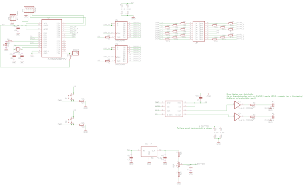
The schematics look the following:
The ATMEGA328 has port PB2 (SS), PB3 (MOSI) and PB5 (SCK) connected to the SPI bus of the LTC6903.
Further two push-button are connected to increase or decrease the frequency.
The two 7 segment displays are connected via two 74HC164 shift registers. The displays show the frequency which is set.
With the push-buttons the frequency can be controlled from 0.1 MHz to 1 MHz in 0.1 MHz steps, from 1 MHz to 68 MHz in 1 MHz steps.
For finer frequency settings the generator can be connected via the serial port to a computer and can be controlled via a serial interface. In this way the full frequency range of the LTC6903 can be explored.
The two outputs CLK and CLK_BAR are connected via a buffer to a SMA connector. The buffer voltage can be controlled by a potentiometer in order to change the amplitude of the output clock. The output is a square wave but can be converted into a sine way by an external filter.
The designed board can be seen in the following:
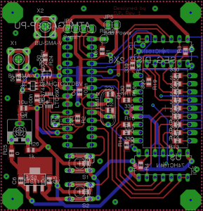
|
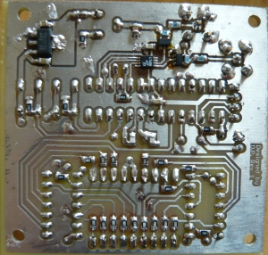
|
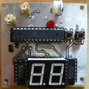
|
|
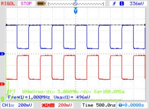
Looking at a 1 MHz signal generated, one can clearly see that channel 2 is the “not” of channel 1:
The microcontroller is programmed using the Arduino language:
#include <SPI.h>

const int slaveSelectPin = 10;

const int SegDisp1Pin=2;
const int ClkPin1=3;
const int SegDisp2Pin=4;
const int ClkPin2=5;

const int PushButton1Pin=6;
const int PushButton2Pin=7;

const long MaxFreq=68000;
const long MinFreq=1;

int FirstDigit=-1;
int SecondDigit=-1;

long value=1000;//in kHz
boolean FirstLoop=true;

int LastButtonState=LOW;
long ButtonPushCount=0;


void setup()
{
  pinMode(SegDisp1Pin, OUTPUT);      // Pin of the Segemt Display 1
  pinMode(ClkPin1, OUTPUT); //Clock Port
  pinMode(SegDisp2Pin, OUTPUT);      // Pin of the Segemt Display 2
  pinMode(ClkPin2, OUTPUT); //Clock Port

  pinMode(PushButton1Pin, INPUT); //PushButton1
  pinMode(PushButton2Pin, INPUT); //PushButton2

  //SPI
  // set the slaveSelectPin as an output:
  pinMode (slaveSelectPin, OUTPUT);
  // initialize SPI:
  SPI.setBitOrder(MSBFIRST);
  SPI.begin();


  Serial.begin(115200);        // connect to the serial port
  Serial.println("Welcome Frequency Generator\n\n");
  Serial.println("Enter Frequency  in kHz: ");
}


//Table to translate to 7 Segment display
byte getCodedNumber(int i){
  byte b =B00000000;

  switch (i) {

  case -2:
    b = B11111011;//"0." Zero with a dot
    break;
  case -1:
    b = B00000000;//all segemnts off
    break;
  case 0 :
    b = B11111010;//0 MSB first
    break;
  case 1 :
    b = B00100010;//1
    break;
  case 2 :
    b = B01111100;//2
    break;
  case 3 :
    b = B01101110;//3
    break;
  case 4 :
    b = B10100110;//4
    break;
  case 5 :
    b = B11001110;//5
    break;
  case 6 :
    b = B11011110;//6
    break;
  case 7 :
    b = B01100010;//7
    break;
  case 8 :
    b = B11111110;//8
    break;
  case 9 :
    b = B11101110;//9
    break;
  default :
    b = B00000000;//
  }
  return b;
}

void fullShiftReg(int Pin,int ClkPin, int value){
  byte b=getCodedNumber(value);

  for (int i = 0; i < 8; ++i) {
    digitalWrite(ClkPin, LOW);

    if (b & (1 << i)) {
      digitalWrite(Pin, LOW);//Low let the LED turn on
    }
    else {
      digitalWrite(Pin, HIGH);
    }
    //delay(100);
    digitalWrite(ClkPin, HIGH);
    //delay(100);
  }
}

boolean ButtonIsPushed(int ButtonPin){
  if(digitalRead(ButtonPin)==HIGH){
    if(LastButtonState==LOW){//Check if we released the button in the meantime or push for longer time
      LastButtonState=HIGH;
      delay(100);
      return true;
    }
    else{
      ButtonPushCount++;//count how long the button is pressed
      delay(100);
      if(ButtonPushCount>20000){
        return true;
      }
      return false;
    }
  }
  else{//Button is not pressed
    LastButtonState=LOW;
    ButtonPushCount=0;
    return false;
  }
}

//Wite frequency to the SPI bus
void SPIWrite(byte Byte1, byte Byte2) {
  // take the SS pin low to select the chip:
  digitalWrite(slaveSelectPin,LOW);
  //send the 16 bits in two bytes
  SPI.transfer(Byte1);
  SPI.transfer(Byte2);
  // take the SS pin high to de-select the chip:
  digitalWrite(slaveSelectPin,HIGH);
}

//Generate the bit pattern for the frequency setting
void calculateFreqSet(long value){
  //We need to calculate in Hz here

  int myOCT=(int)((double)3.322*log10(value*1000./1039.));

  int DAC=(int)round(2048-(2078*pow(2,(10+myOCT)))/(value*1000));

  //Check boundaries
  if(DAC<0) DAC=0;
  if(myOCT<0) myOCT=0;
  if(DAC>1023) DAC=1023;
  if(myOCT>15) myOCT=15;

  //Define the conf bits (last two bits)
  byte CNF =B00000000;

  //int is 16 bits
  //Shift the bits to the right position
  unsigned int BitMap=(myOCT<<12)|(DAC<<2)|CNF;

  //convert into two bytes
  byte Byte1=(byte)(BitMap>>8);
  byte Byte2=(byte)BitMap;

  SPIWrite(Byte1, Byte2);

}

void loop()
{


  long NewValue=value;

  if(Serial.available () > 0){
    NewValue=Serial.parseInt();//Read in the value
    while (Serial.available() > 0) {
      Serial.read();
    }
  }


  if(ButtonIsPushed(PushButton1Pin)){//up count
    if(value<=900){//All values below one Mhz are incresed with the pushbutton by 100kHz to full x*100kHz values
      NewValue=(value/100)*100+100;//here we make it a full 100kHz value and add 100
    }
    else if(value<=67000){
      NewValue=(value/1000)*1000+1000;//here we make it a full 1MHz value and add 1MHz
    }
  }

  if(ButtonIsPushed(PushButton2Pin)){//down count
    if(value<=1000&&value>100){//All values up to one Mhz are decresed with the pushbutton by 100kHz to full x*100kHz values
      NewValue=(value/100)*100-100;//here we make it a full 100kHz value and subtract 100
    }
    else if(value<=68000&&value>1000){
      NewValue=(value/1000)*1000-1000;//here we make it a full 1MHz value and subtract 1MHz
    }
  }

  if(NewValue!=value || FirstLoop==true){//value changed or first loop
    FirstLoop=false;

    if(NewValue>MaxFreq || NewValue<MinFreq){
      Serial.println("Frequency out of range!");
    }
    else{
      value=NewValue;
      Serial.print("Frequency set: ");
      Serial.print(value);
      Serial.println("kHz");

      //Set the oscillator
      calculateFreqSet(value);

      if(value<1000){//100Khz
        FirstDigit=-2;
        SecondDigit=value/100;
      }
      else if(value>=1000 && value<10000){//Mhz
        FirstDigit=-1;
        SecondDigit=(value/1000)%10;
      }
      else if(value>=10000){//10Mhz
        FirstDigit=(value/1000)/10;
        SecondDigit=(value/1000)%10;
      }

      fullShiftReg(SegDisp1Pin,ClkPin1, FirstDigit);//Fill second digit
      fullShiftReg(SegDisp2Pin,ClkPin2, SecondDigit);//Fill first digit
      delay(100);

    }

    Serial.println("Enter Frequency in kHz: ");
  }
  else {
    delay(100);
  }

}
[1] https://groups.google.com/forum/#!topic/sci.electronics.design/UMFw1Vz3fZg
[2] http://www.linear.com/product/LTC6903
The design files can be downloaded from GitHub
https://github.com/digibird1/FrequencyGenerator
It can be checked out with:
git clone https://github.com/digibird1/FrequencyGenerator
Hi, nice work
Why you dont use phase accumulator in fpga? its easy and yo can get better resolution.
Some tutorial and source code from tarp http://verilog.openhpsdr.org/
Hi Tomas,
thanks!
The main reason why I’m not using an FPGA is that I wanted something standalone and simple. Just something you connect the cable and get a signal out, for example to test if my ADC get the signal, or if a mixer is working. No computer, or serial connection needed, and the parts required are basically only the small oscillator, the rest was available in my spare part box.
Signal generator, great idea.
I dont know who you are, but I am learning so much from your blog. Whereever you are on this planet, I wish you are doing well. Wishes from Singapore.
the way you have shared PCBs schematics allow newbies like us to really go in and undertand the fundementals. This blog is a sea of knowledge. Thank you so much for your hardwork. You have made the world a better place.